System Airflow
The HVAC system has to move enough air across the coil to deliver the efficiency it was rated for. We measure total system airflow and compare it to the minimum CFM per ton of nominal cooling capacity — 350 for new construction, 300 for alterations.
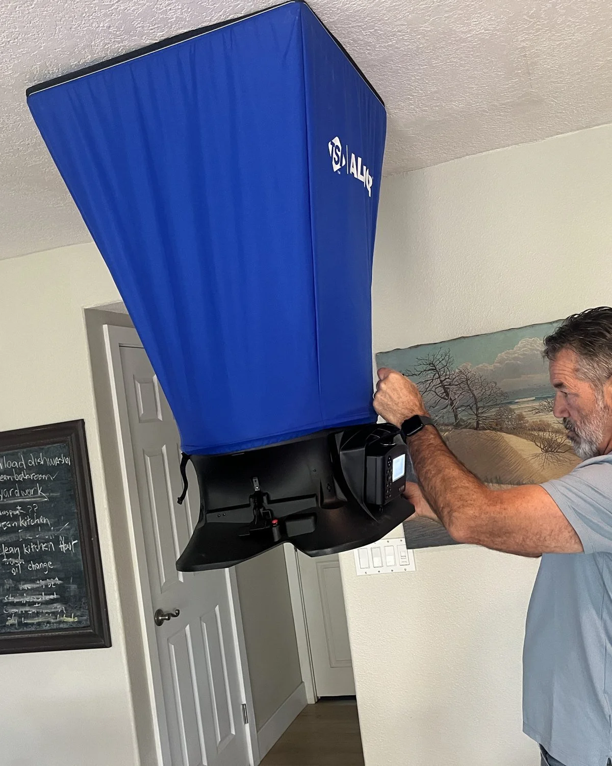
Minimum airflow
Per ton of nominal cooling capacity, measured with the system in cooling at its highest fan speed.
| Project | System | Minimum | Code |
|---|---|---|---|
| New construction | Standard ducted | 350 CFM/ton | §150.0(m)13 |
| New construction | Small duct high velocity | 250 CFM/ton | §150.1(c)7A |
| Alteration | Standard ducted | 300 CFM/ton | §150.2(b)1F |
| Alteration | Small duct high velocity | 250 CFM/ton | §150.2(b)1F |
What to expect
How we measure airflow when you hire us.
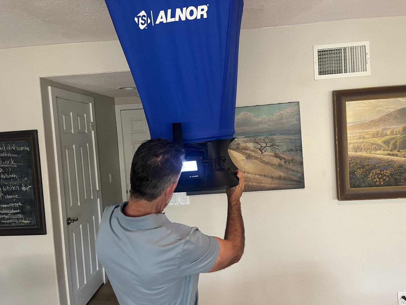
Measured at the returns
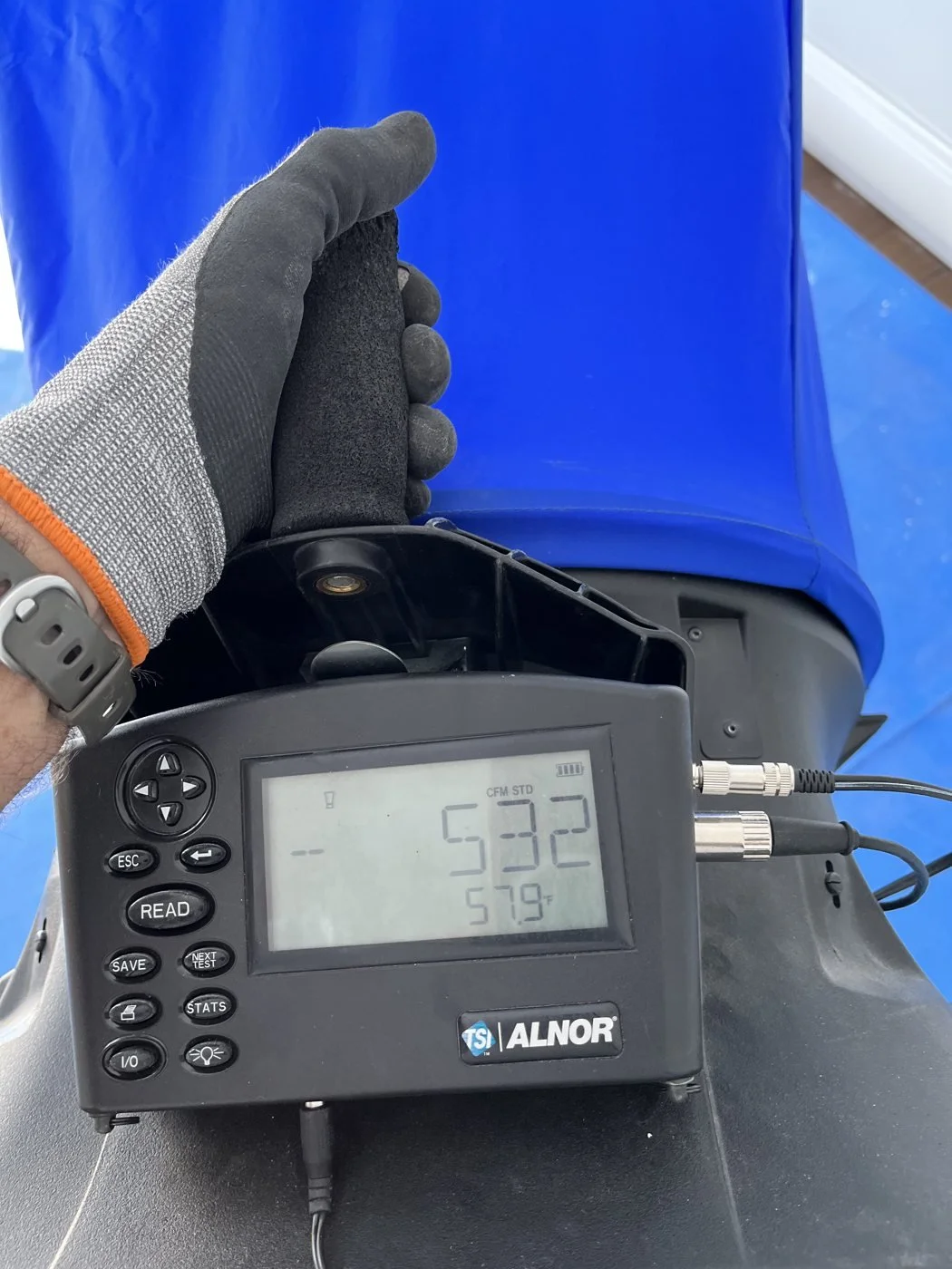
With the system running in cooling at high speed, we measure total airflow at the return grille(s) with a calibrated flow capture hood — or with a flow grid at the filter slot when the return can’t be captured. The total is divided by the system’s nominal tons and compared to the minimum.
Results on record
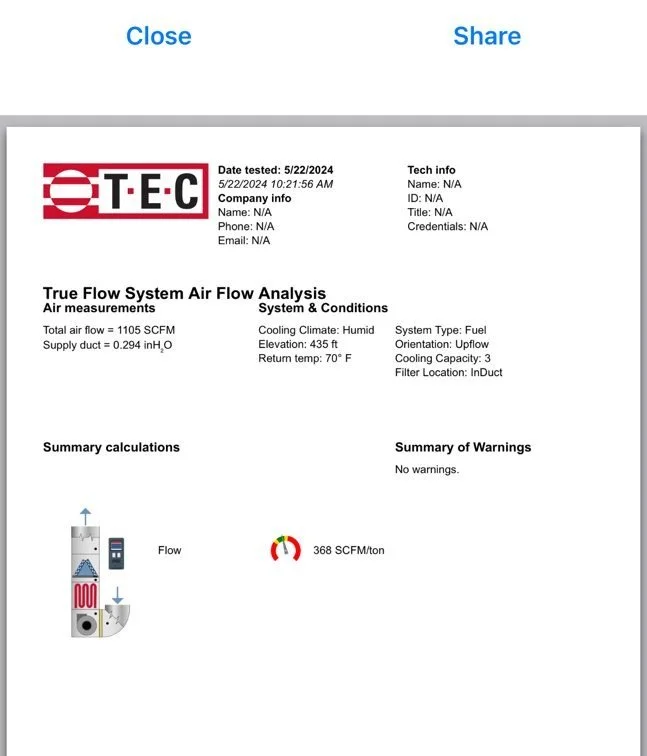
Every reading is recorded with the system’s tonnage and the calculated CFM per ton, and registered in CHEERS on the CF2R/CF3R. If an altered system can’t reach 300 CFM/ton, the installer works through the code’s remedial checklist — filter, registers, coil, blower speed and return sizing — before charge is verified at the highest airflow attainable.
The code
Click a section to read the actual code language, or open it in the official CEC document.
§150.0(m)13New construction: airflow and fan efficacy
Exception 1: Standard ducted systems (without zoning dampers) may comply by meeting the applicable requirements in Table 150.0-B or 150.0-C as confirmed by field verification and diagnostic testing…
Exception 2: Multispeed compressor systems or variable speed compressor systems shall verify air flow (cfm/ton) and fan efficacy (Watt/cfm) for system operation at the maximum compressor speed and the maximum air handler fan speed.
§150.2(b)1FAlterations: minimum airflow
Exception 1: Systems unable to comply with the minimum airflow rate requirement shall demonstrate compliance using the procedures in Section RA3.3.3.1.5; and the system’s thermostat shall conform to the specifications in Section 110.12.
RA3.3.3.1.5Altered systems that can’t reach the minimum
RA3.3.3.4.3Compliance criteria
Common failures & how to avoid them
What actually fails in the field — and how to avoid it.
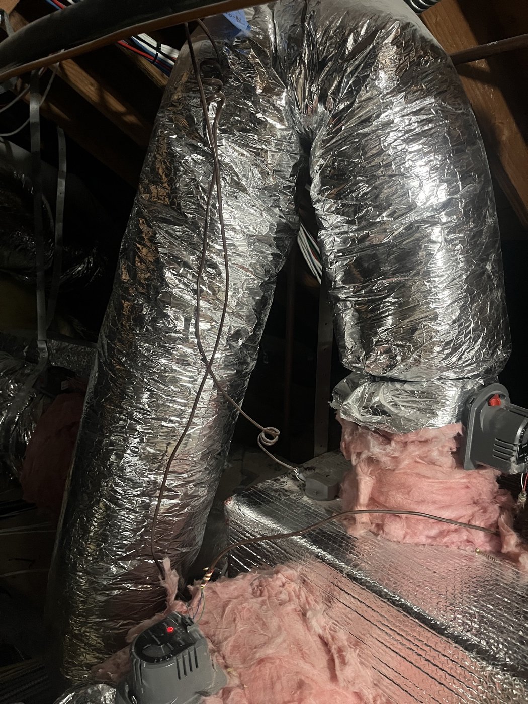
- Poor duct installation. Kinked, crushed or pinched flex, sharp bends at the boots and plenum, and long sagging runs all choke airflow.
- Returns too small — or too few. The return side is where most systems come up short. One undersized return can’t move the air the system needs, no matter how good the supply side is.
- Fan speed set too low. The blower is left on a low speed tap for cooling, so the system never reaches its rated airflow.
- Pull flex tight, support it properly and keep it straight — no kinks or hard bends at the connections.
- Size the returns for the system’s airflow (see the table below) and add a second return when one can’t do it.
- Set the blower to the correct cooling speed before the test.
Duct size vs. airflow
| Duct diameter | Airflow (CFM) |
|---|---|
| 4″ | 20 CFM |
| 5″ | 50 CFM |
| 6″ | 80 CFM |
| 7″ | 120 CFM |
| 8″ | 170 CFM |
| 9″ | 230 CFM |
| 10″ | 300 CFM |
| 12″ | 500 CFM |
| 14″ | 740 CFM |
| 16″ | 1,050 CFM |
| 18″ | 1,400 CFM |
| 20″ | 1,875 CFM |
Schedule airflow testing.
Airflow and fan efficacy are verified together once the system is running.